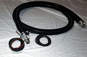
Stainless Steel Braided Heated Hose Fittings
Selecting the proper fittings for a heated hose application is largely determined by mating the fittings to which the heated hose assembly will be attached. Once the mating fittings have been identified, the heated hose fittings should complement the mating fittings in type, size, and alloy. Even though the selection of heated hose fittings is determined by the mating fittings, it is a good idea to confirm that the fittings used in the application are appropriate for the application and any necessary changes made. Ensure that the fittings are chemically compatible with and are able to withstand the pressure and temperatures of both the media and the surrounding environment.
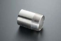 |
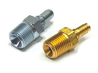
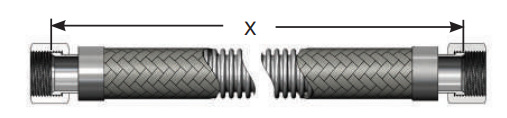
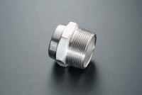
Male Pipe Nipple
|
 |
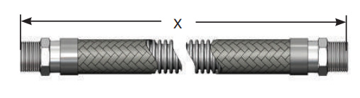
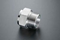
Hex Male
|
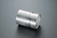 |
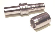
Grooved-End Fitting
|
 |
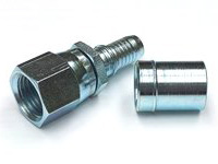
LiveLink® Swivel Fitting
|
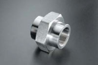 |
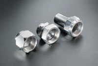
Female Union (Threaded/Socket Weld)
|
 |
Female Half Coupling (Threaded/Socket Weld)
|
 |
1, 2, or 3 Piece SAE (JIC)
|
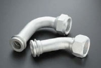 |
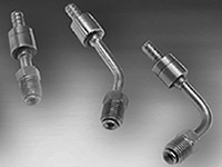
45° and 90° SAE (JIC)
|
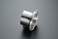 |
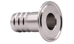
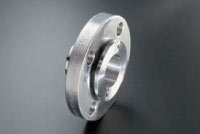
Sanitary Flange
|
 |
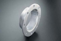
Slip-on Flange
|
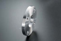 |
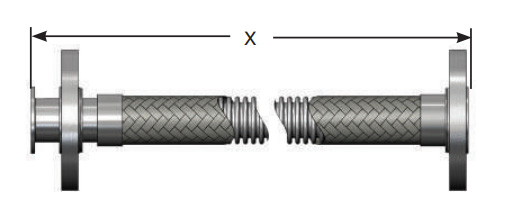
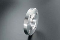
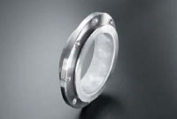
Plate Flange
|
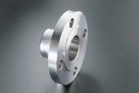 |
Weld Neck Flange
|
 |
TTMA Flange
|
 |
C Stub with Floating Flange
|
 |
A Stub with Lap Joint Flange
|
 |
TTMC C Stub Swivel
|
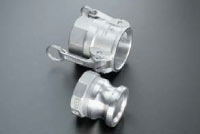 |
Part A and Part D (Cam-Lock)
|
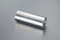 |
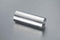
Tube End
|
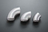 |
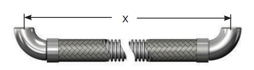
Short and Long Radius Elbows (45° and 90°)
|
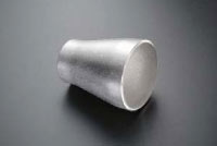 |
Reducer
|
 |
Beveled Pipe End
|
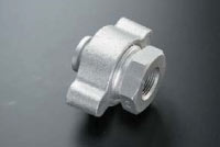 |
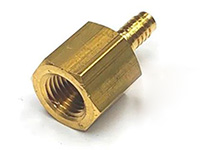
Ground Joint Female
|
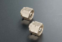 |
Specialty Gas Nuts
|